|
|
|
The communications standard "DMX512" covers digital
multiplexed signals. It is the most common
communications standard used by lighting and related stage equipment.
DMX512 provides up to
512 control "channels" per data link. Each of these
channels was originally intended to control lamp dimmer levels. You
can think of it as 512 sliders on a lighting console, connected to
512 light bulbs. Each slider's position is sent over the data link
as an 8-bit number having a value between 0 and 255. The value 0
corresponds to the light bulb being completely off while 255
corresponds to the light bulb being fully on.
DMX512 data is transmitted at 250,000 bits
per second using the RS-485 transmission standard over two wires. As
with microphone cables, a grounded cable shield is used to prevent
interference with other signals.
There are five pins on
a DMX connector: a wire for ground (cable shield), two wires for
"Primary" communication which goes from a DMX source to a
DMX receiver, and two wires for a "Secondary"
communication which goes from a DMX receiver back to a DMX source.
Generally, the "Secondary" channel is not used so data
flows only from sources to receivers.
DMX512 is connected
using a daisy-chain methodology where the source connects to the
input of the first device, the output of the first device connects
to the input of the next device, and so on. The standard allows for
up to 32 devices on a single DMX link. Although each device has an
input and output connector, these are merely wired together -- no
re-transmission or amplification is performed by each device.
Each receiving device
typically has a rotary switch which sets the "starting
channel number" that it will respond to. For example, if
two 6-channel dimmer packs are used, the first dimmer pack might be
set to start at channel 1 so it would respond to DMX channels 1
through 6, and the next dimmer pack would be set to start at channel
7 so it would respond to channels 7 through 12.
The DMX512 communications protocol is very simple and robust. It involves
transmitting a reset condition (indicating the start of a new
"packet"), a start code, and up to 512 bytes of data. Data
packets are transmitted continuously. As soon as one packet is
finished, another can begin with no delay if desired (usually
another follows within 1 ms). If nothing is changing (i.e. no lamp
levels change) the same data will be sent out over and over again.
This is one of the best features of DMX512 -- if for some reason
the data is not interpreted the first time around, it will be
re-sent shortly.
Not all 512 channels need
to be output per packet, and in fact, it is very uncommon to find
all 512 used. For example, most simple lighting consoles only
output 16 channels or less. The fewer channels are used, the higher
the "refresh" rate. It is possible to get DMX512 refreshes at
around 1000 times per second if only 24 channels
are being transmitted. If all 512 channels are being transmitted,
the refresh rate is around 44 times per second.
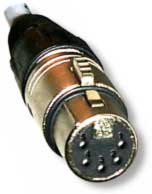 Standard DMX connectors use XLR connectors with
five pins: Standard DMX connectors use XLR connectors with
five pins:
-
Pin 1: Shield (ground)
-
Pin 2: Primary Data Complement (-)
-
Pin 3: Primary Data True (+)
-
Pin 4: Optional Secondary Data Complement (-)
-
Pin 5: Optional Secondary Data 2 True (+)
A DMX output connector is always female, and a
DMX input connector is always male. Some manufacturers use 3-pin XLR
connectors, eliminating Pins 4 and 5.
The DMX512 signal is
transmitted via the industry standard interface EIA485, more
familiarly known as RS485. RS485 is a balanced connection. The
standard wiring is a twisted-pair, shielded, low-capacitance data
cable designed for RS-485 -- never use standard microphone cable.
Recommended cables are Belden 8227,
Belden 9156, Belden 43906
(European DMX Cable Version).
Data is transmitted in
serial format asynchronously with the transmission speed of 250
Kbps. Voltage on both pins ("+" and "-") should
be between +12 volts and -7 volts (measured to ground). EIA485
defines that the signal voltage between the two wires should be at
least 200 millivolts. Higher voltage on the "+" pin and
lower voltage on the "-" pin results in a digital
"1". Higher voltage on the "-" pin and lower
voltage on the "+" pin results in a digital "0".
The ground wire is only a reference point and often used for
shielding.
DMX devices such as
lights are connected in a daisy-chain fashion: from the controller
to light #1, to light #2, to light #3 and so forth. According to the
standard, a DMX512 controller can only drive up to 32 loads (e.g.,
one light = one load). But improvements in technology have reduced
the load a single light puts on the circuit, so you may be able to
drive as many as 128 lights (each one being 1/4 load) from a single
controller such as the QM2000 board. To control additional loads
(lights), a DMX splitter is required.
The final device in the
daisy-chain must be terminated. Terminating plugs contain a 120 ohm resistor
soldered across pins 2 and 3. The terminator functions by absorbing
signal power which would otherwise be reflected back into the cable
and degrade the data.
DMX512 was created in 1986 by the United States Institute for
Theatre Technology (USITT)
as a standardized method for connecting lighting consoles to
lighting dimmer modules. It was revised in 1990 to allow more
flexibility.
The Entertainment
Services and Technology Association (ESTA)
has assumed control over the DMX512 standard. At this writing (May
2000), ESTA is making revisions to clarify and further extend the
standard. Special care is being taken so that existing DMX512
equipment will work under any new standard. So there is no need to
hold off on implementing the existing DMX512 standard, or on buying
existing DMX512 devices -- these will work fine under any new
revision.
ESTA refers to the
current draft revision as the "BSR 1.11 -- DMX-512/2000"
standard. The draft is being taken through the rigorous process for
establishing consensus so it may become an American National
Standard. The draft may be available for public review sometime
between August and December 2000.
-
DMX512 is a method of connecting a single controlling source
to multiple receivers
-
Serial data can be sent up to 4000 feet over microphone-like
cables
-
Up to 512 devices, or functions on a device, can be controlled with 8-bit
resolution
-
All channels are continually being "refreshed",
which increases safety
-
Although the DMX512 standard is being updated, existing
equipment will still work the same under any new revision.
Next
page: DMX devices >
|