|
|
|
Projector
Connections:
|
|
|
|
|


| During the 22 years that I�ve been a part
of the laser display industry, I have offered my knowledge and
assistance freely. One of the things that I am known for is
helping people with their scanners. Laserists and scanner
manufacturers alike have been sending scanners to me for
years, so that I can tune them for optimal performance and
make other modifications when necessary. Most often, I do this
as a free service for ILDA members.
One thing that I have noticed in recent years is that people are having more difficulty with connecting the various components together to make a complete laser projector. Incorrect connections can lead to distorted images and other problems, which are then mistakenly blamed on poor scanner tuning or poor component performance. Incorrect connections can also lead to a dangerous projector � for example, one which will output a beam even when it is not connected. For this reason, it is quite often that when I receive a projector or scanning system to tune, I wind up re-wiring the components so that the projector can produce perfect images. Since so many people seem to have difficulty in this area, I decided to write an article that shows the proper way to connect the components together. This article is intended to be a guide for projector manufacturers on the best way to assemble components to create a laser projector conforming to the ILDA Standard Projector (ISP) specification. It may also be interesting to many laserists, as it provides a good insight into how projectors work and the components involved. When discussing the connections inside a laser projector, it is best to conceptually separate these connections into two categories: Connections that are related to power supplies (referred to as �Power Connections�); and connections that are related to the ILDA DB-25 signals (referred to as �Signal Connections�). We will discuss the power connections first.
POWER CONNECTIONS
Figure 1
Figure 1 shows the general manner in which power connections should be made between the various components. We will discuss the connections for the scanner power supplies first, because they are at the top of the diagram, and also because once that foundation is laid, the other power connections can be easily understood. Power enters the projector from the AC Mains Supply. An integrated switch and fuse assembly is often used as shown. The international color standard specifies the brown wire as the LINE (or �Hot�) lead, and the blue wire as the NEUTRAL lead. These are connected to the power supply LINE and NEUTRAL connections respectively. If you look closely at the power supply, you should see the words �Line� and �Neutral�, or letters �L� and �N� that designate which wire goes where. Note that there are AC power cords that do not have polarized plugs, and these two may become swapped at the point that the projector plugs into the wall. However, you should still maintain a sense of �Line� and �Neutral� throughout the laser projector, always connecting the �Line� terminals of all power supplies to the same (preferably brown) wire, and �Neutral� terminals to the other (preferably blue) wire. The most important difference between the �Line� and �Neutral� connections, is that the �Line� connection is the one that you use when connecting a switch and fuse in line with power supplies. With laser projectors whose optical output power is relatively low (for example, a few hundred milliwatts) and projectors that have a plastic enclosure, there may only be two AC power wires (Line and Neutral) and the Ground wire may or may not be used. For projectors that have a metal enclosure, a Ground wire (international color code is green as shown) must always be used and connected as shown. The Power Connections diagram shows two separate power supplies used to generate +24V and �24V for the scanner amplifiers, but this could be embodied as a single power supply that generates both voltages as indicated by the light gray box. In either case, the +24V and �24V power wires are connected from these power supplies to the scanner amplifiers. As with the power supplies, the scanner amplifiers may also be embodied as two separate single-axis amplifiers, or as one dual-axis amplifier as indicated by the light gray box around them. The most important part of Figure 1 is the �Central Grounding Point�. This is really the single most important connections concept inside the laser projector, and the thing that many people do not initially understand. Basically, any component inside the laser projector that requires a ground connection should make a �home-run� to the �Central Grounding Point�. This connection scheme is called a �Single-Point Grounding Scheme� which is also known as a �Star Grounding Scheme�. The �Central Grounding Point� should be located close to the power supplies. Unlike the +24V and �24V, which can simply be connected to the scanner amplifiers in a daisy-chain fashion as shown, the ground connections (designated PG in the diagram for �Power Ground�) require more careful consideration, and must each make a �home run� type connection to the �Central Grounding Point�. When an AC ground connection is used (green wire on the diagram), the easiest thing to do would be to connect it to the �Central Grounding Point� as well. This is because, often times this �Central Grounding Point� is eventually (through �phantom ground connections�) connected to the optical plate within the projector. If �phantom ground connections� can be completely prevented, then the AC ground connection could simply be connected to the projector chassis, but not to the central grounding point. This provides the best performance, but requires the most careful projector design and layout, and close attention to detail in terms of avoiding �phantom ground� connections. See the section on �Avoiding phantom ground connections� later in this article. When an AC ground is not used, or when the AC ground is connected only to the projector chassis and there are absolutely no �phantom ground connections� then ILDA DB-25 pin 25 MUST be connected to the �Central Grounding Point�. Note that the ILDA DB-25 pin 25 should NOT be connected to the �Central Grounding Point� if the AC ground connection is already connected there, otherwise there will be a ground loop formed external to the projector, which is undesirable.
WHY USE A SINGLE-POINT GROUNDING SCHEME
Figure 2
To understand why it is best to use a single-point grounding scheme, take a look at Figure 2, which shows a power supply connected to a single-axis scanner amplifier. Each of the wires that connect the scanner amplifier to the power supply will have some finite amount of resistance As an easy-to-understand example, let�s assume that each wire has a resistance of 1 ohm. During strong accelerations that occur when the beam is commanded to jump from one side of the projection area to the other, the scanner amplifier will momentarily require high peak currents from the power supply. Typically these peak currents could reach up to 4 amps. If the wires that connect the power supply to the scanner amplifier are 1 ohm, this will momentarily raise the voltage on the �Power Ground� connection to 4 volts! (This is referred to as �Ground Bounce�.) If this �Power Ground� signal is then �daisy-chain� connected to another scanner amplifier, or to other components inside the projector, then those other projector components will also momentarily experience a voltage of 4 volts, thus corrupting the signal integrity of the other components. When a single-point grounding scheme is used, the �Ground Bounce� stays localized to the particular projector component that generated it (in this case, the X scanner amplifier), thus preventing the �ground bounce� from corrupting other projector signals. And since the scanner amplifier has differential inputs, the amplifier itself will be able to subtract out the �ground bounce�, thus maintaining its own signal integrity. This illustrates why a single-point grounding scheme is the best way to connect projector components. Without this scheme, images often appear distorted, as shown in Figure 3:
Figure 3
A scan fail
monitor may also be connected to the scanner amplifiers as
shown on the diagram. This is required for audience-scanning
projectors, and might also be advisable for graphics
projectors as well. Most scan fail monitors connect to the
same power supply that operates the scanner amplifiers. In any
event, the ground connection of the scan fail monitor must
make a �home run� connection to the �Central Grounding Point�
as shown on the diagram. POWER CONNECTIONS FOR THE LASERS In addition to showing the connections for the scanner power supply, Figure 1 also shows the connections for the lasers. However, unlike the connections for the scanner amplifiers, the connections shown for the lasers are intended to be more conceptual than literal. The reason is because, although scanner amplifiers are highly standardized and generally all require the same kind of power supplies and connections, the lasers themselves may have integrated AC power supplies and laser diode drivers, or may each operate on a separate power supply and driver. The diagram
shows a single power supply operating three solid-state laser
diode drivers, but there may be only a single laser, or in
fact the laser may be an ion laser with completely separate
power supply. Nevertheless, the diagram shows conceptually
what must be accomplished for best results. If the laser power
supply is small enough to fit within the projector, then the
�Power Ground� from the power supply, as well as the �Power
Ground� from the laser diode driver should each be routed to
the �Central Grounding Point�. If an ion laser were used, then
a PCAOM would be used to modulate the beam. In this case, you
would connect the Power Supply of the PCAOM driver, as well as
the PCAOM driver each to the �Central Grounding Point� using a
�home-run� type connection. PROJECTOR INTERLOCK (required by the ISP standard) Figure 1 also shows a relay placed in series with the laser power supplies. This relay is intended to facilitate the �interlock� feature of the ILDA Standard Projector. When connected as shown, the laser diode drivers (and optionally, the shutter driver) will only receive power when the interlock loop is closed. The interlock facilitates an additional layer of safety for laser projectors, and is required by the ISP standard. The interlock facilitates an additional layer of safety for laser projectors, and is required by the ISP standard. The interlock signals form a �loop� that starts at the laser projector, goes through all of the cabling that connects the projector to the signal source (often a computer), and goes right back to the laser projector. If this loop is broken somehow, for example by someone tripping over the signal cable, the projector should not output light. It is also possible for users to place a �Red Mushroom Switch� in series with the ILDA cable and connected to the interlock lines. This provides an easy mechanism for laser operators to prevent laser output when needed. And lastly, since the connector on an ILDA Standard Projector is a DB-25, which is the same connector used by desktop computers for SCSI, Printer, and Serial connections, it is possible that someone might mistakenly plug the laser projector into one of these connectors. The SCSI, Printer, and Serial DB-25 connectors all output some kind of signals, and thus, might cause light to be emitted from the laser projector. The interlock portion of the ISP standard is intended to help prevent light from coming out of the projector if the projector is mistakenly connected to a non-laser signal source. Although it is shown in the diagram as a relay, which applies or removes power from reaching the laser diode drivers, the interlock system may be implemented in other ways, including as an additional shutter within the projector. The ISP specification allows for voltages up to 25 volts, and currents up to around 160 milliamps to exist on the DB-25 pins. Thus, the projector interlock must be facilitated in such a way that these values are not exceeded. However, I recommend that you try to implement an interlock that uses far less voltage and current � for example 5 volts and 5 milliamps. This could be done using an electronic relay instead of an electro-mechanical relay. The interlock signals may also be implemented using other methods that might provide an increased level of safety � for example, by outputting a small sine-wave signal on pin 4, and comparing it to the voltage received on pin 17. It is also a good idea to put an LED or some other indicator somewhere within the interlock system so that the user can see when the interlock is enabled or disabled. In the diagram, we show an LED connected as the Laser Emission Indicator. SIGNAL CONNECTIONS
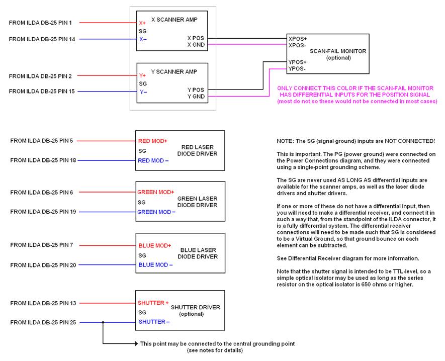
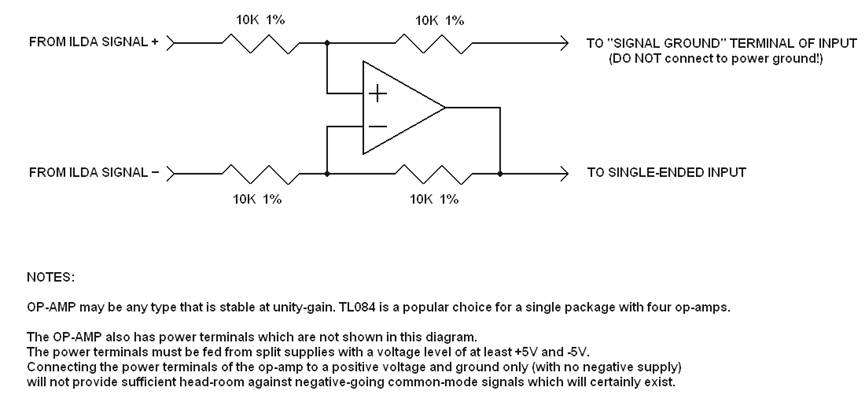
Figure 4 We will now discuss the connections that are related to the ILDA DB-25 signals, starting with a discussion of the scanner amplifiers. The ILDA DB-25 connector primarily contains signals that control the motion of the beam (i.e. X-Y scanning), and the color and brightness of the beam (i.e. R, G, B beam power). There are other signals on the DB-25, such as the projector interlock mentioned above, a shutter signal, and some multi-propose �user� signals, but this article only discusses motion and color related signals, as well as the shutter and projector interlock. The motion- and color-related signals are arranged as differential pairs. For the purpose of the laser projector, the word �differential� means that the laser projector must derive the actual signal level by taking the difference between two signals (i.e. by subtracting). For example, ILDA DB-25 pin 1 contains the X+ signal, and pin 14 contains the X- signal. Often times, when pin 1 is going from 0V to +5V, pin 14 will be going from 0V to �5V. The actual signal level is found by subtracting; thus +5V minus �5V = +10V. This means that the voltage level that the X scanner amp should sense is +10V. Note that I used the term �often times� above. The reality is that there is no strict requirement for the X- signal to be �equal but opposite� when compared to the X+ signal. As far as the projector is concerned, the same X position could be commanded if the X+ signal goes to +10V and the X- signal stays at 0V, because +10V minus 0V = +10V. Likewise, the same result could be generated if the X+ signal goes to +20V and the X- signal goes to +10V, because +20V minus +10V = +10V. This is an important concept, because the ISP standard absolutely requires projectors to derive all motion and color signals by taking the difference between two signals. No motion or color signal should be assumed to be referenced to ground, and � within the projector � no motion or color signal should be connected to ground. With that in mind, you will notice that we connect ILDA DB25 pin 1 to the X+ input on the X scanner amplifier, and we connect pin 14 to the X- input. One thing that is not shown in the diagram, but could be handy to have is an �Invert switch� on the projector. This switch should be placed in the path of the X+ and X- signals, so that you could easily invert the projected image if needed. The ILDA ISP standard states that the beam should move to the right, when there is a positive differential signal on the X input. This provides correct orientation for a front-projection scenario. For rear-projection, the polarity of the X axis will need to be inverted, and the �Invert switch� allows this to be accomplished very easy. What�s more, an �Invert switch� often comes in handy when doing dual projector audience scanning type displays. For the Y axis, we connect pin 2 to the Y+ input of the Y scanner amplifier, and we connect pin 15 to the Y- input. Note that, although the scanner amplifiers themselves may have a �Signal Ground� input (labeled SG in the diagram), this is NOT connected!! The reason this is not connected is because if it were, this would destroy the single-point grounding scheme that was established and discussed above in the Power Connections section of this article. Basically, since the scanner amplifiers have differential inputs, it is only those differential inputs that are used for ILDA DB-25 signals. The only ground connection is made from the �Power Ground� to the �Central Grounding Point� already mentioned above. If a scan-fail interlock were used, it would be connected to the X POSITION and Y POSITION signal from the scanner amplifier. But, there is something tricky to watch out for. You should consult the manufacturer of the scan-fail interlock to determine whether or not the scan-fail interlock itself has a differential position input. If the scan-fail monitor does not have a differential position input, you should NOT connect the �Signal ground� or �Position ground� from the scanner amplifier to the scan-fail monitor. Doing so would, again, destroy the single-point grounding scheme. The scan-fail monitor already has a ground connection to the �Central Grounding Point� established on the Power Connections diagram. You should only connect the scan-fail monitor to the scanner amplifier�s ground connection if the scan-fail monitor itself has differential inputs. Pangolin�s PASS safety system does have a differential position input, but most others do not. The scan-fail monitor would also be connected to a shutter or to the laser diode drivers, but the method of connection depends on the exact scan-fail monitor being used. Consult the manufacturer of the scan-fail monitor for details. The color signals are connected in exactly the same way as the X and Y signals were connected, using differential signaling. ILDA DB-25 pin 5 is connected to the �positive modulation input� on the red laser diode driver, while pin 18 is connected to the �negative modulation input�. ILDA DB-25 pin 6 is connected to the �positive modulation input� on the green laser diode driver, while pin 19 is connected to the �negative modulation input�. ILDA DB-25 pin 7 is connected to the �positive modulation input� on the blue laser diode driver, while pin 20 is connected to the �negative modulation input�. The discussion about color signals above, as well as the diagram makes the assumption that the laser diode driver has differential inputs to begin with. As two examples, laser diode drivers made by Laserwave and by Viasho do have differential inputs, but, as two other examples, laser diode drivers made by CNI and Melles Griot do not. Also, it is possible that the laser projector would have an ion laser and PCAOM used for color modulation. In this case, the same connection scheme and discussion applies. PCAOM drivers made by NEOS do have differential inputs, but PCAOM drivers made by AA do not. (In general scanner amplifiers to have a differential input, however some very low cost scanner amplifiers may not.) Since the ISP standard absolutely requires all motion and color signals to be implemented as differential pairs within the projector, this means that if you have scanner amplifiers or laser diode drivers that do not have differential inputs, you will need to implement the differential receiver as a separate circuit. One easy way to do this is with a difference amplifier, as shown in Figure 5, below. A single op-amp along with four resistors can be used to receive the differential signal from the X, Y, R, G, or B signal, and generate a �single ended� signal which is then connected to the scanner amplifier or laser diode driver. Note that this circuit is drawn and implemented in such a way that it has two inputs and also two outputs. One of the outputs is the �single-ended� signal that drives the component, but the other output is a �ground reference�. This needs to be connected to the �Signal ground� input terminal of the scanner amplifier or laser diode driver. The connection is made this way in lieu of connecting this to any other ground, so that �Ground Bounce� can be detected and rejected by this circuit. Also note that this diagram does not show the pin numbers of the op-amp, and also omits the op-amp power supply connections for clarity. The op-amp must receive power from a power supply that is capable of feeding it a minimum of +5V and �5V.
Figure 5, Difference Amplifier TTL VERSUS ANALOG COLOR MODULATION (avoiding fires!) The ISP standard requires the color signals to respond in an analog fashion, such that 0V does not produce any light from the projector, 2.5V produces around half the nominal laser power, and 5V produces the full laser power. The ISP standard also assumes that if the laser projector is disconnected from the signal source, there should be NO light coming out of the laser projector (because there would be no difference between the differential color signals). I have recently seen several projectors that used laser diode drivers that used TTL modulation inputs rather than analog modulation inputs. TTL modulation basically means that the laser can be fully on, or fully off. This does not conform to the ISP standard. However, what�s worse is that the TTL modulation inputs �float high�, which means that when the projector is disconnected from the signal source, it produces a full-power, non-moving beam. On a recent trip, I saw this happen on two separate occasions, by projectors made by two separate companies. And in both cases, the non-moving full-power beam landed on dark fabric, which actually caught fire!! One thing to
keep in mind: under very bad circumstances, laser projectors
may present hazards. Projectors must be designed to be safe,
and one of the safety aspects is to prevent light from coming
out of them when the projector interlock is opened, and when
they are not connected. TTL modulation should really be
avoided, but if it is used, at the very least, a differential
receiver should be used which would force the TTL lasers to
�float low� instead of �float high�. SHUTTER AND DB-25 COMMON SIGNALS The ILDA DB-25 pin 13 provides a signal to control a shutter, but its presence is somewhat optional, and may depend on local or federal laws where the laser projector is to be used. For example, for projectors that use solid-state lasers, it might be argued that between the fast and complete extinction offered by the laser diode driver itself, coupled with the fact that the projector interlock actually removes the power from the laser diode drivers, a shutter is therefore not needed. But for ion lasers, even those modulated by a PCAOM, a shutter would still be desired. In general, it can be said that the shutter offers an additional layer of safety for the laser projector, and thus it is a desirable thing to have. Unlike the motion control signals, and color control signals, the shutter signal is not considered to be an �analog� signal. It is TTL in nature, and thus, the shutter is either fully opened, or fully closed. The shutter is fully opened when pin 13 is roughly 5V when compared to pin 25. Also, the shutter signal is not a true differential signal, since noise immunity is not really needed, due to the fact that it is TTL in nature. However, for the purpose of projector connections, it should be considered to be a differential signal whose counterpart is pin 25. ILDA DB25 pin 25 is considered to be the �Common� signal of the ILDA connector. However, this �Common� signal is not necessarily a �Ground� signal, since, under many circumstances, this signal is not connected to �Ground� within the projector. Since the
shutter signal is TTL in nature, and referenced to DB-25 pin
25, one good way to receive this signal is using an optical
isolator. The optical isolator will receive the TTL-level
signal between pin 13 and pin 25 and allow isolation of these
signals from the rest of the projector components. DB-25 CONNECTORS For
projectors, the ISP specification states that the DB-25
connector should be a male connector. However, I recommend
putting two connectors on the projector � one male, and one
female. This maximizes ease-of-use because it allows the use
of any type of DB-25 cable between the projector and signal
source, and also allows easy daisy-chaining of multiple
projectors when needed. BEWARE OF PHANTOM GROUND CONNECTIONS Above we have discussed the benefits of using a single-point grounding scheme. One thing to be aware of is that even when the wire-connections are made carefully, it is possible that the components themselves might provide phantom connections to ground, thus destroying the single-point grounding scheme and creating more of a spider-web-shaped grounding scheme. For example, this would happen if the metal housing of a DPSS laser is connected to the laser diode driver�s ground connection. A phantom ground connection would be made by screwing the metal DPSS laser housing down to the metal base-plate in the laser projector. Therefore, when assembling the laser projector, you will need to use an ohm-meter, to identify which components have metal parts connected to the electrical ground, and which might come in contact with the base-plate, or other conductive projector parts. Once such parts have been identified, they should be isolated from the projector base-plate. I always recommend using nylon spacers under any laser, to
provide a physical and electrical separation between the laser
and the base-plate. The metal case of scanners, and thus, the
X-Y mount of the scanners are another notorious place to
generate a phantom ground connection, and this should be
isolated where possible. OTHER PROJECTOR PARTS THAT MAY BE NECESSARY In addition to the fundamental components described above which are certainly a part of most laser projectors, additional components might also be needed or desired. For example, the United States and certain other countries require additional safety features for laser projectors, including �laser emission indicator�, �key-switch�, �cover interlock�, �external interlock�, �time delay� and a �manual reset�. The laser emission indicator was described above. The other elements are described below.
The key-switch, cover interlock and external interlock are all easily understood and implemented, but the time delay and manual reset provide some difficulty since off-the-shelf components such as laser diode drivers do not have a time delay or manual reset feature. Often times these two features are implemented in the form of an electronic circuit made by the projector manufacturer. As a point of
interest, Pangolin�s
Professional Audience Safety System (PASS) incorporates
differential receivers for both the color signals and position
signals, and also implements the time delay and manual reset
features, thus, this multi-purpose projector control board can
help to solve some of the most difficult problems in
constructing a projector. CONCLUSION Lasers are able to create stunning high-visibility graphic displays, as well as breathtaking audience scanning displays. Lasers serve a niche that can�t be accomplished by any other light form. Getting the connections right inside a laser projector will ensure maximum quality of the projected image, as well as a safe display for all.
|
Copyright 2008, Pangolin Laser Systems. All rights reserved. Reproduction in whole or in part in any form or medium without express written permission from Pangolin Laser Systems is prohibited.